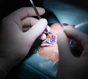
BACKGROUND
To accurately reflect small changes in pressure, a pressure regulator must have a symmetric diaphragm that is uniform in its composition and is as thin at 0.1mm. A large quantity of these diaphragms are made from liquid silicone rubber. Although it is a rather stable process, there are several factors that are considered when molding such a thin part. With a slight misalignment of the mold, the diaphragm membrane will possibly not behave as expected, or worst yet, fail to hold a seal. Additionally, in mass production, the seal must be consistent between parts so that the device can operate as expected with multiple production runs of the component.
PROBLEM
Two key factors in the proper injection of a silicone part are cavity or mold half alignment and the type of gate used. In silicone injection, the silicone will begin flashing with any gap greater than about 0.004-0.005 mm. 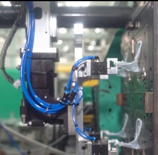 Even a small miscalculation will lead to massive flashing and defective parts. The difficulty is only compounded when a main constituent of the cavity is to mold a membrane only 0.1mm thick. The two different gate types, open gate and valve gate, will be a deciding factor in the equality of the parts.
SIMTEC SOLUTION
For the cavity alignment, two different methods are used to hold the tight tolerances needed for zero flash. Two different locating mechanisms are used to guide the mold into place. First, there is a square side lock. The square side lock is machined to a tolerance of 0.001mm which allows a consistent position. Furthermore, a square side lock is selected because it will provide two surfaces of contact even when the mold halves are slightly different in temperature. A commonly used guide alone is not enough in silicone molding, so in addition to the square side lock, a cone locator may be used to fine tune the cavity position when in the final stages of closing.
Even when the cavities are perfectly aligned to form a uniform part, there has to be something to maintain the equilibrium between cavities. If a valve gate is used, there will be no inter-cavity connection. Even more problematic is that each cavity may then be adversely affected by the valve, since when the gate is closed after injection, the silicone has no place to go during heat expansion. This will cause distortions in the final part, as the material is forced to fold on itself. Another factor to deal with is there will always be a small vulcanized component. The vulcanized component forms at the gate and will be the first thing pushed into the cavity during injection, which could cause blockage in the cavity. The open nozzle system, on the other hand, allows silicone to flow back into the cold runner and balance between cavities when the silicone is expanding. Also, the vulcanized silicone is ejected with the part as a gate vestige, so there is no vulcanized material injected first in an open nozzle system.